
Head-in-Pillow (HIP) Defects: When BGA Geometry Meets Temperature Physics
By Foresite
Introduction
As Ball Grid Array (BGA) packages increase in size, density, and complexity, solder joint reliability is increasingly shaped by interactions between package geometry, material behavior, and thermal conditions during reflow. One of the most challenging failure modes arising from these interactions is the Head-in-Pillow (HIP) defect.
HIP defects are difficult to detect using standard inspection methods and often do not manifest until after deployment. Rather than resulting from obvious process failures, HIP defects emerge from small deviations in coplanarity, temperature uniformity, or timing during a narrow reflow window. Understanding HIP therefore requires examining both thermal and mechanical behavior during soldering.
Mechanism of HIP Formation
A reliable BGA solder joint requires synchronized melting of the solder ball and solder paste, followed by wetting, collapse, and intermetallic formation. In HIP conditions, this sequence is disrupted.
During reflow, the solder ball and paste may independently reach liquidus, but package warpage, localized lifting, or uneven thermal expansion can cause a brief loss of contact at the critical moment. The displacement required is extremely small—often well below visual detectability—yet sufficient to prevent coalescence.
If separation occurs while the solder ball is molten, surface tension can elongate the ball. As the assembly cools, the ball may settle back toward the pad, creating the appearance of a completed joint. Without sustained contact during the molten phase, however, a continuous intermetallic bond does not form.
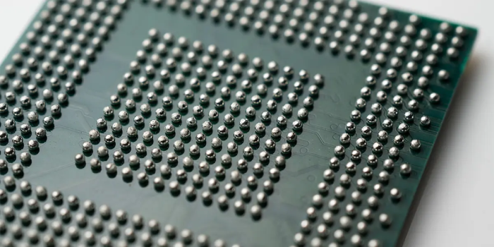
Observed Solder Joint Characteristics
HIP defects exhibit distinct features under X-ray imaging and cross-sectional analysis. Partial HIP conditions often show elongated or necked solder balls, indicating tensile stress during reflow and mechanical separation in the molten state.
HIP defects are frequently concentrated near the corners of large BGA packages, where warpage and mechanical stress are greatest. In these regions, joints may show incomplete bonding, limited intermetallic growth, or partial separation.
In severe cases, complete HIP defects are observed. Cross-sections reveal near-spherical solder balls and separate solder deposits on the pad, confirming that the ball and paste were never molten together.
Susceptibility of Large and High-I/O BGAs
The risk of HIP formation increases with BGA size and I/O count. Larger packages are more prone to warpage due to mismatches in coefficient of thermal expansion between the package substrate, mold compound, and PCB. Achieving uniform heating across large solder arrays also becomes more difficult.
As mechanical and thermal complexity increases, the reflow process window narrows. Small differences in melting timing between solder paste and solder ball can be sufficient to initiate HIP, particularly in marginal process conditions.
Challenges in Detection
HIP defects are difficult to detect. Visual inspection is ineffective due to the hidden nature of BGA joints, and conventional X-ray imaging may show acceptable alignment and apparent contact. Electrical testing can also miss HIP defects if intermittent contact exists at the time of test.
Failures often emerge later during thermal cycling, vibration, or operational stress. Assemblies may pass manufacturing screens yet fail prematurely in the field.
Failure Analysis and Process Correlation
Reliable identification of HIP defects requires advanced failure analysis. High-resolution X-ray imaging can reveal solder elongation and abnormal joint geometries, while cross-sectioning confirms whether intermetallic bonding occurred. These findings must be correlated with reflow profiles, component design data, and material selections to determine root cause.
Linking physical evidence to process conditions allows differentiation between HIP driven by thermal imbalance, package warpage, solder behavior, or combined effects.
Conclusion
Head-in-Pillow defects demonstrate how minor deviations during reflow can create significant long-term reliability risks. They arise not from gross process failures, but from subtle mismatches in temperature, timing, and mechanical stability during a critical soldering window.
As BGA geometries continue to evolve, ensuring solder joint integrity requires careful control of reflow conditions and a thorough understanding of component mechanics. Analytical methods that verify metallurgical integrity—not just visual acceptability—are essential for managing HIP risk.